Powerful UV nitrogen laser for pumping dye lasers
Usually, building lasers involves buying an expensive or rare laser medium such as a crystal or a gas tube. However, with nitrogen (N2) lasers this is not true: You don’t need expensive materials or mirrors, which makes it a popular build choice for laser enthusiasts. In this article, I show a stepped up version of the classic design, which is powerful and reliable enough to pump laser dyes.
How does a nitrogen laser work?
Before we get into the design of the setup, let's first briefly look into the physics of N2-lasers. The gain medium, obviously, is nitrogen. Once an electron hits the molecule with sufficient velocity, it transfers its kinetic energy to the nitrogen which then enters an excited state (E3).
This excited state is the upper laser level (ULL) of the laser system (N2-lasers are three level lasers). When the ULL is populated fast enough (within its lifetime τULL), there will be more electrons in the excited state than in the energy level below it. This state is called population inversion and leads to light amplification within the medium because incoming photons (e.g. created by spontaneous emission) hit the excited atoms, causing them to also emit photons of the same wavelength by stimulated emission whilst transitioning to the lower energy level (E2 in this case). This wavelength, for N2-lasers, is 337.1 nm which is ultraviolet.
τULL is critical for laser performance since it essentially is the time available to build up the population inversion. The longer it is, the easier it is to reach high amplification and therefore output power. In N2-lasers, τULL is dependent on the pressure of the gas (τULL in ns, p in bar):
This means, τULL will be only around 2.6 ns at atmospheric pressure. This sets high requirements for the pumping system. We can relax these requirements a bit by reducing the pressure: At 100 mbar, τULL is about 15.8 ns. However, τILL is around 40 μs, which is about 3 orders of magnitude longer. This leads to the energy level E2 filling up and preventing population inversion between E3 and E2 and therefore quenching laser action. Only after enough atoms have transitioned from E2 to E1 (non-radiantly) population inversion and thus laser action can happen once again.
From this knowledge, we can deduce two important properties of N2-lasers:
- Pumping them requires intense, very fast pulses of high velocity electrons. Therefore, in order to properly pump the upper laser level, low rise-time, high voltage pulses are required. The pulses have to be low rise-time to allow all of the pump energy to be transferred within τULL.
- Since τULL<<τILL , the laser is self-terminating and can only operate in pulsed mode.
Laser design
In this section, the design of the laser system is discussed. I will first go through the electronics and then show the mechanical setup.
Electronics
Note: This section is inspired by Leslie Wright’s implementation of a TEA-N2-Laser.
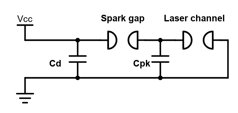
As explained in the previous section, very sharp high voltage pulses are required for pumping, which in this case are created by a charge transfer circuit. This circuit mainly consists of two capacitors (dumping and peaking capacitor), a pressurized spark gap and the laser channel itself, which I will discuss in more detail in the following section.
The charge transfer circuits shown above works as follows: The dumping capacitor Cd is charged by a high voltage source. Once the sparkgap reaches the breakdown voltage (in this case around 15 kV depending on pressure), the peaking capacitor Cpk is very rapidly charged. It in turn discharges through the laser channel, exciting the contained gas.
The entire circuit must be constructed in a way that reduces parasitic inductance as much a possible since inductance, resisting the change of current flow, broadens the pulsewidth and there reduces laser efficiency. Therefore, Cd consists of doorknob capacitors which are connected to each other and the spark gap by a wide and flat aluminium strip. The spark gap is pressurized with nitrogen, reducing the gap length and thus its inductance. Cpk consists of a copper plate which is separated from the base plate (ground potential) by a 190 µm Mylar sheet. This plate is directly soldered to the laser channel plate. The laser channel consists of two parallel copper plates which are separated by around 1 cm (For pictures, see next section).
The concrete values of the source voltage, Cd, Cpk, laser channel width and nitrogen pressure can be chosen using the following rules of thumb:
- The ideal ratio of electric field to pressure is around 120 to 150 V/cm-torr. For a chosen separation of channel width of 1 cm and 15kV spark gap breakdown voltage, the gas pressure should therefore be around 100 mbar.
- Cpk should be around 60pF/cm-1. For a chosen channel length of 200 mm, this results in 1200 pF for Cpk.
- Cd should be 2-4 times Cpk. For the values given above this would be 2400pF - 4800pF.
- The thickness of the Mylar foil must withstand the voltages. For 15kV, 190 µm proved to be sufficient.
- The plate dimensions for Cpk can be calculated using the formular for plate capacitors and the used dielectric (e.g. 0.19 mm thick mylar).
Because the copper plate for Cpk warped during soldering, its capacity is measured at only around 500 pF in my case. Cd is 2400 pF. Despite these unideal numbers, the systems works well which shows the robustness of the design. For the power supply, I used a variable high-voltage (up to 35kV) power supply and a 120kOhm current limiting resistor.
Mechanical setup
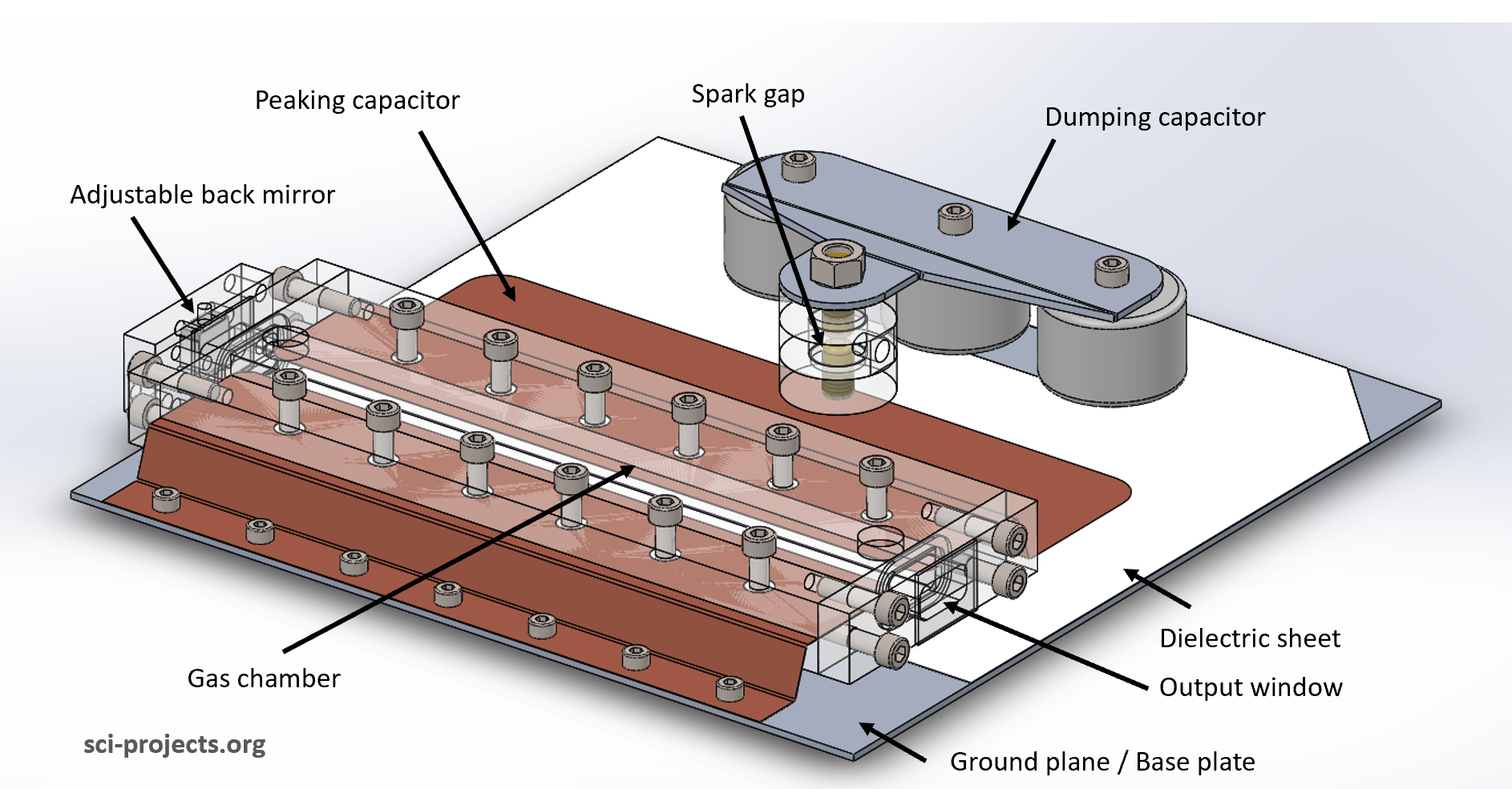
The following picture shows a CAD model of the mechanical setup of the laser system.
All of the components are screwed onto an aluminium plate which also acts as the ground plane. Not using any cables here significantly reduces the systems inductance. The sparkgap consists of a housing made of CNC-machined acrylic pieces which were glued together using cyanoacrylate glue. The electrodes are threaded brass rods with rounded ends. The lower electrode is glued into the housing and the second electrode can be adjusted by screwing it in or out. It its then fixed by a nut. Some high viscosity vacuum grease (Dow-Corning high vacuum grease) acts as a thread sealant. The spark gap can be pressurized to about 3-4 bar.
The gas chamber consists of two CNC-machined acrylic halves and endcaps. The channel electrodes are made of copper sheet. They are aligned to be as parallel as possible and then clamped between the halves using M5 screws, a lot of vacuum grease and high screw torque. The peaking capacitor discharges across the electrodes, which explains the name of the system: Transversely Excited at Reduced Pressures (TERP). The endcaps are screwed on the same way, but they do contain slots for O-rings to increase the sealing capability. The chamber windows are made out of 1 mm thick microscope slide pieces which showed high transmission for UV in previous tests. These pieces are glued onto the endcaps. On one side of the gas chamber is an adjustable back mirror arrangement using M4x0.35 screws and a UV-enhanced aluminium mirror from Thorlabs. Finally, two threaded holes at the top allow for pumping down the chamber. The system can be pumped down to around 50 mbar quite easily but unfortunately does not hold the pressure very long after the pump is switched off.
Attached to the setup is a small nitrogen bottle (usually for welding). A pressure regulator allows for up to 5 bar at the output. The output is directly connected to the spark gap but also to a needle valve. This valve allows for very fine adjustment of nitrogen flow into the gas chamber. See the picture below for a schematic of the pneumatic system.
Results
In the last section of this article, we will look at the lasers performance and a few applications for a setup like this.
As you can see in the picture above, the output beam is stretched and generally of poor beam quality. This is typical for nitrogen lasers. It is noteworthy that the beam you are seeing here is not the laser output itself: The UV beam, which itself is invisible, hits the paper and excites the fluorescent dyes it contains. This method of making the beam visible is quite simple and effective.
The setup can reach a pulse frequeny of about 3 Hz, depending on the setting of the HV-source. The output pulses are quite powerful, surpassing my previous TEA-version by a lot. Depending on the pressures, misfires (no or weak lasing) do still happen frequently but don’t affect the overall performance that much. Flushing the system with nitrogen by opening the needle valve may have a small effect but not as much as others hobbyists have reported (at least for my case).
The picture below shows the entire setup in action:
Overall, the laser’s performance (power and reliability) is quite satisfatory: The high peak power pulses are quite enough for pumping fluorescent dyes such as Coumarin-1, Rhodamine 6G, Rhodamine B and Fluoresceine. Nitrogen lasers are a very typical pump source for dye lasers, which is my initial reason for building this laser.
Since the beam is already around 1 cm long, only a simple cylindrical lens is necessary for focussing the beam into a normal 10 mm quartz cuvette filled with the laser dye:
The sharply focussed UV-beam creates a channel of excited dye which acts as the lasing medium. Because of the high pump powers, the amplification within the dye is so high that the reflectance of the cuvette walls is sufficient for lasing. In the picture below I show this happening with Rhodamin-B dissolved in ethanol. I have also used Coumarin-1, Rhodamine 6G and Fluoresceine for blue, yellow and green outputs, see the GitHub page for more details and pictures.
In a future article, I will give more details about the dye lasers pumped by the N2-TERP-Laser. I will also try embedding the laser dyes into epoxy resin to create solid state dye lasers.
Until then, thank you so much for your interest!
~Nik


